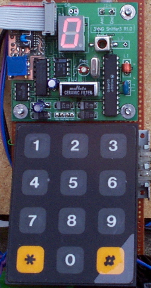
The VK3YNG sniffer MK3

Note: This board is no longer available. This information is included here as support for those who currently use them.

Specifications:

PCB Dimensions:
61mm(H) x 66mm(W) x 17mm(D)
Sensitivity:
better than -110dBm
Attenuation Steps:
7, approx 15dB/step
Maximum input level:
>+17dBm
Frequency coverage:
144-148MHz (140-149.995MHz - reduced spec)
Channel Bandwidth:
±13KHz min.
Supply:
9 volts DC
Low battery warning:
Approx 7.5V
Current:
65mA typ (depends on selected range)
Running time:
>3 hours continuous from Alkaline PP3 battery
      

What else you will need

The board is supplied as a fully built, aligned and tested assembly using surface mount technology with parts mounted on both sides of the PCB. A completed sniffer requires the addition of  a 9V battery and battery holder, power switch, speaker, BNC socket and shielded box. A fully frequency agile sniffer also requires a 12 key matrix keypad similar to that used on a telephone. A limited number of units will come supplied with a small waterproof speaker. For ARDF use, the addition of an earphone socket should also be considered. The LED display is adequate for night foxhunting. For ARDF use, a high efficiency display such as the Hewlett Packard HDSPH101 (Farnell electronics P/N 324-723) should be considered. No soldering is required to change the display.

Making it all work:

Power and Speaker Connection

The sniffer requires connection of a 9V battery and power switch. There is no reverse polarity protection on the sniffer board. Diode protection is recommended before the power switch.

The speaker should be of 8 ohms or greater impedance. The connections for the speaker and power are found near the bottom centre of the PCB. From left to right, the connections are:

Speaker Output Speaker Ground
Supply Ground
Supply input (+9V)
                

Antenna Connection:

A BNC socket is recommended for the antenna connection. JP4 to the top left of the PCB is for antenna connection. The wires from JP4 to the BNC socket should be kept under 10mm long unless coax cable is used for the connection.

Box Construction

The choice and size of box is up to the individual. The following guidelines must be taken into account when building a box for the sniffer.
The box must be fully shielded - a plastic box is not recommended.
Keep cutouts for the display and keypad as small as possible. (The keypad may require an additional shielding plate.)
The speaker should face the operator.
The keypad should be easily accessible and mounted close to the display.
Make sure the battery can be easily replaced.

The low battery LED (D3) should be soldered in place when the box is completed. The longer (+ve) lead goes to the right side.

Attaching a Keypad

A 12-key Matrix keypad is required for frequency entry. The matrix keypad is connected via a short length of ribbon cable to a 10-way 2.54mm pitch header (JP2) on the sniffer board. The keypad can be soldered directly to the pins, or preferably plugged onto the pins using a 10-way IDC header (3M No3473 or similar).

Care must be excercised to ensure that RF pickup by the keypad is minimal. If a cutout is used to mount the keypad, a sheet of grounded PCB should be mounted behind the keypad to ensure the sniffer board is shielded from RF pickup. An externally mounted keypad should have ferrite beads placed on each of the connections to the keypad.

JP2 Connector pinout:

 (1) Row 2
 (2) Row 1
 (3) Row 3
 (4) Column 3
 (5) Row 4
 (6) Column 2
 (7) n.c.
 (8) Column 1
 (9) Gnd
 (10) Gnd

Keypad organisation:


Column 1
Column 2
Column 3
Row 1
1
2
3
Row 2
4
5
6
Row 3
7
8
9
Row 4
*
0
#

Sniffer operation.

A 12 key matrix keypad is used to control most of the sniffer's operation. This keypad is optional and is only necessary if a completely frequency agile sniffer is desired. An ARDF version can be built with just two buttons to select either homing beacon or primary ARDF frequencies. A fixed 145.3MHz sniffer needs no buttons at all.

The sniffer is fully auto-ranging. If a signal is received that is greater in level than the currently selected range can handle, the sniffer will immediately back off the gain in steps of approximately 15dB at a time until it can handle the level of the input signal.  Up ranging occurs in less than 150 milliseconds. If a signal disappears, the sniffer waits for 2 seconds and then begins taking out attenuation until the signal can be received.

Predefined channels:

These are preprogrammed channels that can be recalled at the touch of a single button.
The sniffer powers up on channel 1.

Channel 1:    145.300    - (default channel) Local foxhunts, ARDF
Channel 2:    145.700    - ARDF homing
Channel 3:    144.250    - Local foxhunts, old foxes
Channel 4:    146.000    - Mt Gambier
Channel 5:    146.500    - Mt Gambier/Ballarat
Channel 6:    146.550    - Mt Gambier/Ballarat
Channel 7:    145.650    - Morse Beacon
Channel 8:    145.000    - 70cm/1296 down-converters
Channel 9:    146.675    - Foxhunt Liason
Channel 0:    144.000    - Mt Gambier sniffer hunts

Frequency Entry:

Frequencies other than those listed in the predefined channels can be easily entered. Pressing the (*) key will put an "F" on the display, indicating the sniffer is in frequency entry mode. Four digits are then required to be entered in the order:

* - indicates frequency entry
4..7     - MHz digit (0..9 is permissible)
0..9     - 100KHz digit
0..9     - 10KHz digit
0,5     - 1KHz digit

For example, to enter 144.325MHz the sequence * 4 3 2 5 is entered.

If an error occurs while entering frequencies, the sniffer will briefly display the letter "E" and then will then return to the previously selected frequency.

Manual ranging:

Under some circumstances, it may be necessary to defeat the auto-ranging of the sniffer.

Pressing the (#) key puts the sniffer in range hold/manual mode. The sniffer confirms this by briefly showing "r" on the display followed by the current range. The sniffer will stay on the current range, regardless of signal level, until the (#) key is pressed again.

When in range hold/manual mode, an attenuation level can be entered directly. Range 0 through 7 are all valid. Entering range 8 or 9 or pushing the (*) key will result in the sniffer selecting range 7 which is the highest attenuation range available. (approx 100dB) Note that in this mode, frequency entry is defeated until auto-ranging is re-enabled by a second depression of the (#) key. To remind the operator that this mode is selected, the display briefly shows “r” followed by the selected range after each key depression.

Sniffer MK3 schematic

Sniffer 3 schematic

Sniffer MK3 PCB on test board:

Sniffer 3 on test board

Back to other foxhunt projects page