(Revision history updated Oct 2020)
Please note: This manual is for the latest version of sniffer (V4.2 hardware and V4.2.01 or later firmware).
For pricing and more information look here.
For other versions look here.

The VK3YNG Foxhunt Sniffer is a specially designed synthesised VHF direction finding receiver covering 120MHz and 144MHz bands.
The receiver is designed for quickly finding the direction of beacons or hidden transmitters. Anything from distant weak signals to very close "sniffing" of transmitters running many watts of output power can be pin pointed accurately without suffering "overload" problems that plague other designs. Full auto-ranging operation allows the operator to quickly and intuitively locate the source of a signal without twiddling knobs or watching meters. The operator is freed to concentrate on more important things such as negotiating terrain or reading maps.
The unit is also available in a fully tested Board level format for those who wish to integrate the unit into other equipment or build their own housing.
***Note: A
number of features have changed since earlier versions of the sniffer were released.
This manual reflects operation of version 4.2 hardware and cannot be used for
earlier versions of the MK4 sniffer. For a copies of earlier sniffer manuals please refer to the VK3YNG
foxhunt web site.

Introduction
Differences between V4.0, V4.1 and V4.2
Auto Power Down
Low Battery
Indication
Display
Brightness
Reduced
Functionality mode
Quick Button
Reference
Alternative Key Functions
Detailed Button Operation
Mode/Power
switch
Power On
Mode Selection
Power Off
Memories
Recall functions
Store functions
Sync Button
D-Set button
Relative Battery Voltage
indication
Volume Control
Range Control
Peak Hold Mode
Peak range memory
Frequency Entry
Configuring the sniffer
Minimum Filtering
Medium Filtering
Maximum Filtering
Peak Extend Mode
ARDF Mode
Scan Ready Mode
Display Brightness
Reduced
Functionality Mode
Maximising
Battery Life
Sample
antenna designs
Specifications
Block Diagram
Inside
View of Prototype
Links
Revision History
The VK3YNG sniffer is designed to allow quick, easy and accurate determination of the direction of a transmitted signal in either the 120-123MHz or 143-150MHz bands. The sniffer provides enough sensitivity to determine the direction of a signal from many kilometres or miles away. This is useful for ARDF or Radio Sport and general commercial or Civil Air Patrol use. It also provides enough attenuation to accurately determine the direction of signals right up to the source of the signal without suffering from overload or compression effects.
Attenuation (signal reduction) is provided automatically in steps of approximately 15dB each time a particular signal strength threshold is reached. The number of 15dB steps of attenuation is shown on an LED display. For example, a display value of zero indicates maximum sensitivity, where a value of 9 indicates a very strong signal that requires approximately 135dB of attenuation.
Signal strength indication is provided by an audible tone that increases in frequency (pitch) with increasing signal level. This is done because the human ear is a much more sensitive to changes in pitch than sound level. There is also no inertia or overshoot problems as tend to occur with signal meters. A special software algorithm ensures that the received signal strength tone does not suffer from “compression” effects that occur at higher signal levels with some designs.
Differences between V4.0, V4.1 and V4.2
The main differences between the new versions are:
1) The IF section of the sniffer has been redesigned to remove the obsolete LA8608 IF chip. V4.0 uses the NXP SA615 and V4.1 and V4.2 use the AKM AK2365A.
2) The mixer has been redesigned to remove an obsolete GaAsFET mixer. The new mixer has slightly better dynamic (IP3) performance.
3) Attenuation is more consistent between ranges.
4) Default display brightess is now programmable.
5) Version 4.1 and 4.2 use a 45.1MHz IF frequency (V4.0 and earlier used 10.7MHz) to replace obsolete ceramic IF fitters. This results in better image rejection.
6) Version 4.2 uses a Qorvo SPF5043Z LNA replacing the now obsolete NXP BF1212WR used in V4.1 or earlier versions. The SPF5043 LNA gives the sniffer slightly better sensitivity.
7)
A new power supply used in Version 4.1 is rather picky about high
battery voltage and will not start up above about 3.4V. This
causes problems when trying to use single use Lithium batteries which
can have unloaded voltage up to 1.8V per cell. This problem has
been rectified in version 4.2 hardware. All previous versions can use
single use Lithium batteries.
Other than that operation and specifications are largely identical.
When power has dropped to 2.5 volts or lower, the display decimal point is enabled to warn the user that batteries are in need of replacement.
This mode may be useful for children or first time operators. It allows the sniffer to be used in its most basic format and hides all programmability options from the user. This mode is very useful for scout foxhunting for example. For this reason, many refer to this mode as “Scout Mode”.
|
|
|
|
|
|
Recall channel 1 (Hold to store frequency/mode) | Recall only channel 1 |
|
|
Recall channel 2 (Hold to store frequency/mode) | Recall only channel 2 |
|
|
Recall channel 3 (Hold to store frequency/mode) | Recall only channel 3 |
|
|
Recall channel 4 (Hold to store frequency/mode) | Recall only channel 4 |
|
|
Recall channel 5 (Hold to store frequency/mode) | Recall only channel 5 |
|
|
Recall channel 6 (Hold to store frequency/mode) | Recall only channel 6 |
|
|
Band Scan or ARDF mode Start of
cycle
Synchronisation function. |
No function |
|
|
Range down Delay Set/Display. 1
to 5 seconds. 0=peak hold mode. (7-9 are special functions) |
Show relative Battery capacity in % |
|
|
Volume Down | No function |
|
|
Volume Up | No function |
|
|
Manual Range set/disable | No function |
|
|
Frequency Entry (4 digits follow) | No function |
|
|
Power/Audio Mode Select (Tone/AM/FM, Hold for power off) | Power On/Off only (instant power off) |
| Button | Display during power-up | Function if pressed during power-up |
| 1 |
n |
Filter “A”, Minimum Tone filtering. (fastest response) |
| 2 |
o |
Filter “B”, Medium Tone filtering |
| 3 |
P |
Filter “C”, Maximum Tone filtering (slowest response) |
| 4 |
A |
ARDF mode. Synchronised at power-up. Sync key is used to re-sync the transmitter cycle |
| 5 |
C |
Scan mode. Sync key is used to scan for strongest signal between frequency stored in channels 5 and 6. |
| 6 |
J |
Filter “D”, Tone Extend Mode. Used for very short duration signals. (New function in V2.1 firmware) |
| 7 |
H |
(Reset) Normal operation. Resets all options below to default setting: |
| 8 |
L |
Low-Tone mode (RSSI tones at quarter frequency. Resolution slightly reduced at low tone frequencies) |
| 9 | G |
Mt Gambier mode (10-channel special - New in V3.0) |
| 0 |
o,d,b,A | Toggle display default brightess level (off*/dull/bright/Auto) |
| F |
S |
Enable Reduced key functionality mode (“Scout” mode) |
| R |
t |
Enable auto range change announcement tones. (Morse announcements in V4.0) |
Pressing
this button momentarily while the
unit is powered up cycles the unit through its operating modes and
briefly
displays the selection on the display. The modes cycle through in the
following
sequence: “A” – AM reception, “U” – Unmuted FM reception,
“F”
– Muted FM reception and “t” – Signal strength Tone. The cycle
then
repeats. When headphones are used, one channel is always set to give
signal
strength tone, while the other channel follows the selected mode. This
is
useful for hunting different continuous carrier transmissions where the
transmitters’ identification is given using either AM of FM modulation.
Pressing and holding the Mode button for
greater than 1 second will power down the unit. In reduced
functionality mode,
the unit will power off immediately when the Mode button is pressed.
The mode
switch operates only as a simple on/off switch in reduced functionality
mode.
|
|
|
|
|
|
|
|
|
The recalled frequency is not displayed in reduced functionality mode.
The Store function is disabled in reduced functionality mode.
This facility is used to synchronise the receiver for use in international style (ARDF) foxhunting for a one-minute cycle, five-transmitter system.
In ARDF mode this timer is automatically synchronized when the receiver is switched on. Three short beeps are generated as confirmation of this mode. Pressing the Sync button re-synchronises this timer. Three short beeps are given to confirm this button has been pressed. The sync button should be pressed at the start of transmitter one’s cycle.
At 50 seconds into the cycle, the sniffer will generate three short beeps giving 10 seconds warning that the current transmitter’s cycle is about to end. If the sniffer is currently receiving at range 1 or lower, at four seconds before the completion of the current transmitter cycle the sniffer broadcasts a number of beeps corresponding to the number of the transmitter in the cycle which is about to commence. The pitch of these beeps is set slightly lower than the “50-second” beeps. The display also briefly flashes the number of the next transmitter. If a range down delay (d-Set) of zero is selected and the sniffer is not currently configured for manual ranging, the sniffer will automatically select range zero at the start of the next transmitters’ cycle regardless of the current signal strength.
When ARDF mode is not selected, the “7” key performs a basic band scan operation where the sniffer hunts for the highest signal between the two frequencies stored in channel locations 5 and 6. The highest signal found is stored in channel 4. The scan will ignore any signals within approximately 10KHz of the frequency stored for channel 1 and the signal must be detectable at range 2 or higher to be stored.
This operation takes some time to complete, especially if there is large frequency difference between channels 5 and 6. The scan function works best for continuous signals and may not properly detect intermittent transmissions. Channel 5 must be lower in frequency than channel 6 and both frequencies must be within the same band (i.e. 120MHz or 140MHz)
The SCAN mode is entered by pressing and holding the “5” button during power-up. It is cancelled by entering ARDF Sync mode. Scan mode is the factory default.
In ARDF mode, if a range down delay (d-Set) of zero is selected and the sniffer is not currently configured for manual ranging, the sniffer will automatically select range zero at the start of the next transmitters’ cycle regardless of the current signal strength.
Holding the “7” key during power-up cancels the Low RSSI Tone mode, Range Change Announcement tones* and the Reduced Key Functionality mode. In this mode the signal strength tones function normally and the maximum signal strength pitch is 8KHz. This mode is set as the factory default. (*Note: this facility operates differently in older firmware versions)
This key is disabled in reduced functionality mode.
Ranging up on the sniffer happens automatically with minimal delay. To implement short term peak detection, there is an intentional delay before the sniffer ranges down. This delay is programmable between 1 and 5 seconds using the D-Set button. For beginners, a value between 3 and 5 seconds is recommended. For more advanced users, 1 or 2 seconds gives better results. When hunting intermittent and very short duration transmissions such as those used on wildlife, 5 seconds or “peak hold” mode (see below) is recommended. The factory default is 2 seconds.
To set the range down delay, press the “D-Set” button. The display will respond by displaying the letter “d”. Pressing buttons 0 through 5 will then set and store the new range down delay.
Pressing the D-set (8) button twice will briefly display the current range down delay in seconds. The display then reverts to displaying the current range.
Setting a range down delay of zero disables down ranging. In this case the sniffer operates in a “peak hold” mode and down ranging is disabled. Manual ranging is disabled and pressing the “range” button will reset the current peak hold range to zero. This mode is useful when hunting extremely intermittent signals such as Dog Collar, wildlife or model aircraft beacons.
Holding the “D-Set” key during power-up causes the sniffer to operate in lower tone RSSI mode. This mode may prove useful to those who have difficulty hearing higher audio frequencies. In this mode the signal strength tone frequencies are divided by 4. The top tone pitch is limited to about 2KHz and resolution becomes slightly limited at the lowest tone frequencies. (Note: this mode has no effect on the pitch of supervisory beep and tone frequencies)
This key is disabled in reduced functionality mode.
In version 3.0 onwards, if peak hold mode (Dset 0) is selected before the sniffer is set up for reduced functionality (“scout”) mode, the peak hold behavior behaves slightly differently. If a strong signal disappears for more than 5 seconds, the sniffer will range down by one range only. As with normal peak hold behavior it will stay there until the range is reset or the channel or frequency is changed.
This operation was added to give beginners a second go at a signal source if they happen to “over shoot” it and the signal falls below the current peak range.
Pressing the “D-Set” button then pressing “7” will display 4 digits indicating the number of hours and minutes since the receiver was powered up. This can be useful for ARDF events where the user may have forgotten to synchronise their watch.
Pressing
the “D-Set” button then pressing
“9” will display two digits giving an indication of the relative
battery
capacity in percentage terms. 99% indicates a full battery while 0%
indicates
the point where sniffer operation is significantly compromised. The
sniffer may
power itself off before reaching 0%.
Pressing the “D-Set” button and then pressing the “F” button will display 4 digits which indicate the installed firmware version.
These buttons are disabled in reduced functionality mode.
Normally the sniffer automatically selects the best range for the currently received signal. In some situations it may be necessary to range the sniffer manually. The range control button can be used for this purpose. This button also controls a number of other features depending on the mode selected.
In auto-ranging mode, pressing this button briefly displays the letter “r” in the display, and then the display reverts to displaying the current range. Pressing any digit then manually selects the range. The display briefly displays “r” followed by the selected range. The sniffer remains in manual ranging mode until defeated by pressing the “R” button a second time. This re-enables auto-ranging.
Holding
this key during power-up enables announcements of range, frequency and
various other functions using morse code. This feature has replaced the
"be-bop" style range tones announcements feature used in previous
versions. It has been added to better assist blind operators using the
receiver. (Note: This is a new feature in version 4 and its operation
is subject to change. More information on its operation will be added
to the web site soon.) Powering up with the "7" button pressed disables
morse announcments. See the section on configuring the sniffer for more information.)
This key is disabled in reduced functionality mode.
If
the range button is pressed twice in
succession, the display will briefly show the maximum range the sniffer
has
achieved since power up or the last successful frequency change. (In version 3.0 onwards, pressing "Dset" then "Range" also perfoems the same operation).
In ARDF mode, (see Sync button section) the peak range value is automatically reset at 30 seconds into the current transmitter cycle. This is very useful if there is a need to check what range the sniffer got to just before the previous transmitter finished its cycle.
This function is not available when Peak Hold mode (dSet=0) is selected.
Factory default frequencies
|
|
|
|
|
|
|
|
|
|
|
|
|
|
|
|
|
|
|
|
|
|
|
|
|
|
|
|
Note: 121.5MHz is used as an
international personal, maritime and aeronautical distress beacon
frequency. With an appropriate antenna, the sniffer can be used to
locate PLB, ELT and EPIRB emergency beacons.
For the scan function to work correctly,
the frequencies stored in channels 5 and 6 should be in the same band.
This is not the case for the factory default configuration.
Direct
frequency entry is not permitted in reduced functionality mode.
*Note: Some special
versions of the sniffer operate with different frequency ranges to those
indicated above. The label on the rear of your sniffer will indicate the frequency
range your sniffer covers.
Some special
“narrowband” versions also allow 1kHz resolution. In this case the fourth digit
entered can be any number from “0” to “9” instead of only “0” or “5”.
2.5kHz resolution can
be available for some special builds, such as in the United Kingdom and areas of Europe. In this case “2” and “7” are also valid
and correspond to xxx.xx25 MHz and xxx.xx75 MHz respectively.
The MK4 sniffer has a number of configurable features. Some of these have already been described in the previous sections. The rest are explained here.
There are four levels of filtering available on the MK4 sniffer. These are selected by holding buttons 1, 2, 3 or 6 when powering up the sniffer. The sniffer will retain this setting until the next time it is changed.
This level of filtering is the same as the original MK4. It offers the fastest and most accurate tracking of the received signal level. On transmitters with a high AM component, the tone can become quite “thick” sounding as the tone tries to partially track the modulation. This setting is the factory default.
This level of filtering offers the best compromise between response time and Amplitude modulation (AM) filtering.
This mode provides maximum filtering of the received signal and is similar to that of the VK3TJN/XAJ Ultra-sniffer. While this mode offers the best smoothing of received signals it can tend to “blur” the definition of short duration pulses.
This is a special mode for use with very short duration repetitive signals such as those emitted from wildlife or model aircraft transmitters. The transmitters used are typically very low power and transmit for around 40 milliseconds every second or two. The tone pitch and therefore signal direction can be very hard to determine using the above filtering modes.
This special mode extends the time of the peak level of the received signal so that the user can easily compare the signal level from different directions.
Holding the “4” button while powering up puts the sniffer into ARDF mode. In this mode the sniffer will power up giving three beeps and will synchronise the ARDF timer. For more information see the section on the Sync Button.
Holding the “5” button while powering up puts the sniffer into scan ready mode. In this mode the sniffer gives a single beep during power up and the sync button executes a band scan function. This is the factory default. For more information see the section on the Sync Button.
In this mode the signal strength tone frequencies are divided by 4. See the description of the “Dset” button for more info.
This is a special mode was added in the V3.0 (or later) sniffer for Australian Championships “fox-or” foxhunting. In this case the “7”, “8”, “9” and “0” keys are reallocated as fixed frequency channel recall buttons. The sniffer is set up to recall a set of 10 frequencies that match the transmitters used in the Mount Gambier event. This is done without affecting the frequencies stored in the 6 standard memories and resetting from this mode (by powering up with the “7” key) will recall the previously programmed settings. Note that when this mode is set the functions normally allocated to these buttons (Sync, Dset and Volume) are not available.
| Channel Key | Frequency | Channel Key | Frequency |
| 1 |
144.000MHz |
6 |
145.250MHz |
| 2 |
144.250MHz | 7 |
145.300MHz |
| 3 |
144.500MHz | 8 |
145.500MHz |
| 4 |
144.750MHz | 9 |
145.700MHz |
| 5 |
145.000MHz | 0 |
145.750MHz |
In this mode, most of the special features of the sniffer are disabled. This mode is useful when a newcomer or a scout group etc uses the sniffer. (Hence why some users call this “Scout Mode”) Memories can only be recalled and most of the other keys, including volume control are disabled. The power button only acts as a simple on-off and the mode of operation is defined by what is stored for each channel.
To set the sniffer in reduced functionality mode, press and hold the “F” button while powering up.
To cancel reduced functionality mode, press and hold the “7” key while powering up.
This key resets the following modes if set:
1) Low Tone mode,
2) Range Tones Announce,
3) Reduced Functionality (scout) mode,
4) Gambier Mode
There are a number of solutions for extending battery life with the sniffer. The most
critical one is the volume setting. Battery life is reduced considerably when using the
internal speaker on a high volume level with a continuous signal. Use the lowest
volume level possible when using the internal speaker or use external headphones.
The display also operates at a higher intensity level for daytime use that puts more
load on the battery. Typically night time only operation increases alkaline battery life
by about 30%.
Users who would like to get the longest use between battery changes should consider
using Single Use Lithium AA batteries. These batteries have a very long shelf life and capable of
providing well over 14 hours of continuous daytime operation.
Zinc Carbon and General Purpose Manganese, or so called “Heavy Duty” batteries
are not recommended. The internal resistance of these batteries is too high to get
reliable operation from the sniffer.
This version of the sniffer can run off higher
capacity NiMh batteries but this is generally not recommended as their terminal
voltage (1.2V) is normally too low. The power supply module in V3.0 of the
sniffer is capable of operating off NiMh batteries and their use may be
considered if the sniffer is used very regularly. But keep in mind that the sniffer
will always indicate the batteries as partially depleted, even when fully
charged. When the batteries go flat the sniffer will stop operating abruptly
with little or no warning. The sniffer also provides no means of charging these
batteries. They must always be removed for charging.

The above graph shows the discharge rates of the typical battery options. It shows that
the Lithium and 2500mAh NiMh can significantly outperform even the best alkaline
batteries.
The lower published per cell terminal voltage of NiMh (1.2V) can become irrelevant
as time increases since the voltage is essentially constant. Another downside is that
the weight of these high capacity rechargeable batteries is around twice that of
Lithium.
NiMh rechargeable batteries are not recommended for infrequent use. The
self
discharge rate of these batteries will mean that they will go flat
after sitting unused in
the sniffer for several months where Alkaline or Lithium batteries will
maintain their
usability for a much longer period. Note that version 4.1 of the
sniffer is picky about high terminal voltage and will not work with
single use Lithium batteries. This issue does not affect version
3.x or version 4.2
It is always recommended to remove batteries of any type when the sniffer is not in
use for extended periods.
**
Note: Rechargable Litium Ion batteries are not suitable for use in the
sniffer. Their terminal voltage is too high and using them will damage
the sniffer! More information on foxhunting and
techniques can be found on the Australian ARDF website Follow this
link for Pricing, Availability and other foxhunt projects.
To contact the author:
Sample
antenna designs
The antenna design is largely a matter of
personal choice. For portable use, designs vary between two and four
elements. More elements give better directivity and more precise
bearings but are more difficult to carry around. For most situations,
three elements offers a good compromise. Here is an example of antenna
designs for 120 and 146MHz.

Specifications:
*Note: Battery life is dependant
sound level and display intensity. See section on battery life.
Frequency Coverage
Standard version: 120-122.995MHz,
143-149.995MHz in 5KHz steps
Channel Bandwidth
16KHz
Sensitivity
Better than -120dBm
Maximum signal level
Greater than +30dBm
Power Supply
3VDC (2xAA Alkaline or
1.5V Lithium penlight cells)
Battery Life*
Typically 8+ hours
(alkaline), 14+ hours (Lithium)
Memories
6, programmable (stores
mode and frequency)
Receive modes
AM, FM, Signal strength
Tone
Max RSSI frequency
Programmable 2KHz or 8KHz
Size
76mm(W), 80mm(H), 25mm(D)
not
including BNC connector
Antenna Connection
BNC
Headphone Connection
3.5mm stereo
Links:

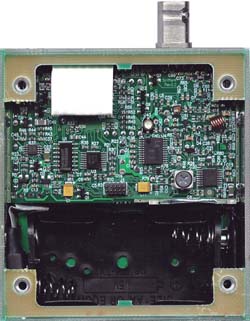

Inside
view of V1.3 prototype (Left) and the V2.2/V2.4 unit. In
both cases not all components are shown as a significant number of them
are on the opposite side of the board. The two images to the right are the new V3.0 unit. The later rev units use fine pitch
IC's and 0603 SMD components to give maximum functionality in a small
package.
Bryan
Ackerly, VK3YNG
Revision History
Manual
Revision
Date
(dd/mm/yy)
Description
1.0
23 Jan 2002
Initial Release of manual
Hardware release 1.0, Firmware release 1.0
1.1
26 Jul 2002
Manual revision 1.1:
- Included quick button reference
details and
rewritten some button function details.
- Added sample antenna designs, block diagram, tips for extending
battery life, links and contact information
Hardware release 1.1:
- Addition of improved VCO module
Firmware release 1.1:
- Added display range display
override.
- Display shows range instead of Tx number in ARDF mode if range goes
up.
- Added ability to see battery voltage in reduced functionality (scout)
mode
- Volume control disabled in reduced functionality (scout) mode.
- Relative battery capacity (0-99%) can be displayed.
- Different tones used for ARDF mode transmitter number announcement
beeps.
- Transmitter announcment beeps now set to four seconds before minute
boundary (was 2 seconds)
- Peak range detector added which holds peak range for 30 seconds in
ARDF mode.
- Range hold mode simulates the “Green button” on the “YQN” sniffer by
using the range button.
1.2
28 Oct 2002
Manual updated to release 1.2 to link with
firmware revision. No code or hardware changes
1.3
02 Nov 2002
Hardware Release 1.2:
- Improved Power Supply noise
filtering
Firmware release 1.3:
- Added auto volume reset (limits
setting to “5”
under low battery conditions)
- Recalling a channel multiple times in the presence of a signal would
cause the sniffer to range up each time a button was pressed and not
range
back down if the channel was recalled more than 9 times in a row. Range
is now reset to zero if the received frequency is changed or preserved
as
is if the same frequency is recalled. Frequency will be displayed if no
range
up is required.
2.0a
13 Oct 2003
Hardware release 2.0
- Processor changed to ATMega8.
Doubled processor speed.
- Receiver redesigned to remove obsolete Motorola MC13135
- New Rx front end and Discrete MOSFET mixer
Firmware Release 2.0.00
- Port to new processor
- Added uptime counter
- Added Band Scan function on sync key
- Added ARDF sync at power-up
- Added "FM Mute" as 4th audio mode
- Added tone filtering features
- Added some handling for UHF operation
- Changed battery capacity lookup table
Manual Release 2.0
- Manual updated to reflect new
hardware and firmware features
- released as pdf only
2.1a
26 Jun 2004
Manual release 2.1a
- Minor manual update
2.2a
25 Oct 2004
Hardware release 2.2
- Replaced Mux and Audio amp IC's
with smaller packages
- Varactors changed
- Replaced MOSFET mixer with GaAsFET part
Firmware release 2.1.01
- Added Filter "D" - peak extend
mode for Wildlife and Model Aircraft hunting.
Manual release 2.2a
- Improved autoranging functionality and range-up speed.
- Released as pdf and html
versions
- Added documentation for "peak extend" tone filtering mode
2.2a
17 Nov 2004
Hardware release 2.2b
- Changes to 2nd IF osc current
for new ref crystals
Hardware release 2.2c
- Improved isolation from
reflected PLL noise (mainly affects 160MHz models)
Firmware release 2.1.02
- alignment tuning range span
changes (120MHz only models)
2.2a
28 Nov 2004
Firmware release 2.1.03
- Added variable peak extend mode
support for 10.7MHz special build (evaluation only).
2.2a
2 Dec 2004
Firmware release 2.1.04
- Minor adjustment to peak extend
tone length
2.2a
5 Dec 2004
Firmware release 2.1.05
- Added support for LMX2316 PLL
for a UHF version (no change for VHF versions)
2.2a
24 Dec 2004
Firmware release 2.1.06
- Upgraded compiler
- Fixed RSSI filter initialisation (minor bug)
- Added independent range alignments for 120/144MHz bands to improve
range 6 overlap on 120MHz.
2.2a
29 Jan 2005
Firmware release 2.1.07
- Added initial LCD support
(requires special hardware build)
2.2a
14 Apr 2005
Firmware release 2.1.08
- Fixed bug for scout mode
powerdown lockup.
(Workaround for earlier versions: Do not store "muted FM"
mode in memory 1)
- Slight reduction in peak extend time
2.2a
10 Jun 05
Firmware release 2.1.09
- Update for internal use. No
change for released version.
2.2a
26 Jun 05
Hardware release 2.2d
- New power supply. Allows
operation down to 2.0V giving much greater battery life.
Firmware release 2.1.10
- Support for new power supply
module
- Added "dead battery" powerdown below 2.0V (was a hardware function
with previous supply)
2.2a
5 Sep 2005
Firmware release 2.1.11
- Added support for 150-153 and
173-180MHz version
2.2a
4 Oct 2005
Firmware release 2.1.12
- Added support for 153-163MHz
version.
2.2a
17 Nov 2005
Firmware release 2.1.13
- Added support for 10.240MHz
reference for 160MHz version.
2.2a
31 Jan 2006
Hardware release 2.3b
- PCB update to integrate rev
2.2d modifications
Fimware release 2.1.14
- Slight improvements to front end amp.
- Range announce display now
works on all ranges when manual range selected
- Added initial 243MHz support for trial use.
- Changed default channel 5 and 6 frequencies for 160MHz version.
2.2a
15 July 2006
Hardware release 2.3c
- Changes to enhance front end
stability and simplify alignment.
Firmware release 2.1.15
- shifted keypad voltages for 4V
supply version. (LCD version support special)
- Added support for 10m and 6m
versions
- added 1KHz resolution support
(requires special "narrowband" hardware)
- added stepped range down delay
(dependent on DSet) for peak extend mode.
- fixed bug where range would not
update immediately after channel recall in "Scout mode"
- fixed flashing "d" segment for
"8" display on special LCD build.
- Added support for narrowband
1KHz step version for 2m Indonesia special build.
- Peak range storage in ARDF mode
now shows peak from last minute for whole minute, not just first 30
seconds.
2.2a
21 Sept 2006
Firmware release 2.1.16
- Added support for narrowband
standard 2m freq range (NZ AR pulsed beacons)
- Added support for narrowband
special 160MHz version (NZ pulsed beacons)
- Fixed bug where ranging would
sometimes go nuts when changing channel from an intermittent
transmitter being received on higher than range 0.
2.2a
27 Feb 2007
Firmware release 2.1.17
- Added support for the same PLL
for both standard and narrow builds. (Used to require use of different
parts)
2.2a
31 Mar 2007
Hardware release 2.4
- PCB update to include rev 2.3c
changes and simplify frequency alignment.
Firmware release 2.1.18
- Lower battery voltage sensing. (Mainly affects LCD build, but also
useful to get more life from alkaline batteries)
- Change to first IF filter to improve adjacent channel rejection and
blocking performance.
- Modified battery voltage
sensing due to resistor value change on rev 2.4 hardware.
- Fixed problem with range 2+ on
frequency boundary with band split (eg 121/144MHz) hardware.
Workaround: Only affects
143.000MHz. Avoid using this freq or use 143.005MHz for older firmware
versions.
- PLL version now handled by
compiler switch. Simplifies updates for hardware prior to rev 2.4
- Fixed frontend alignment bug.
Has no effect for end user.
- Fixed range alignment sweep timing above range 1. Has no affect for
end user.
2.2a
12 Aug 2007
Firmware release 2.1.19
- Added support for switchable IF filter
- Improved range up handling (overcomes transient selection of uncalibrated "range 10")
- Filter forced to 0 during alignment (no affect to end user)
- Default atten range now selectable by build type.
- 151/173 build units default atten range shifted from 6 to 7
2.3
19 Mar 2008
Firmware release 2.1.20
- Range beep now cancelled by "7" key during power-up (Upgrade to manual v2.3 needed)
- Removed the "toggle" for range beep tones selection
- "Simple" mode added for Bigboar build only:
- "Advanced" modes enabled using power up "9".
- "Standard" default modes re-enables using power up "0". (Also restores factory default settings)
2.3
31 Aug 2008
Firmware release 2.1.21
- Removed range "10" from manual ranging unless the build type requires it.
2.3
14 Nov 2008
Firmware release 2.1.22
- Added support for 118-123, 143-148MHz special CAP build (However, scan function doesn't work across the 120MHz boundary)
2.3
26 Nov 2008
Firmware release 2.1.23
- Added support for 155-165MHz Kiwi tracking version
2.3
11 Mar 2009
Firmware release 2.1.24
- Added support for 150-160MHz narrowband for Sweden
2.4
16 Oct 2009
Firmware release 2.1.25
- Added support for illuminated channel button display
- Peak range now displayed using Dset-R
- In scout mode only when using dset-0, the range can only go back 1
range from peak hold value unless frequency is changed or channel is
recalled. (useful to stop sinffer going "Dead" when an inexperienced
user walks right past the signal source.)
- Untested support for manual range keypad LED and button brightness on ADC7 input.
2.4
18 Nov 2009
Firmware release 2.1.26
- Added support for 2.5kHz step for standard UK model.
2.4
11 Nov 2010
Firmware release 2.1.27
- Added support for 2.5kHz step for Italy version.
- Added range 10 support for narrowband version 151/173MHz.
2.4
17 Feb 2011
Firmware release 2.1.28
- Added support for 146-156MHz build.
3.0
15 Dec 2010
Firmware release 3.0.00
- Initial V3.0 Test version
3.0
30 Aug 2011
Firmware release 3.0.01
- Release version
3.0
1 Sept 2011
Firmware release 3.0.02
- Production alignment update. No affect on end user.
3.0
9 Sept 2011
Firmware release 3.0.03
- Added support for 2.5kHz channel spacing version.
3.0
2 Mar 2012
Firmware release 3.0.04
- Added support for special 10-LED channel indication keypad.
- Fixed bug where sometimes channel 1 ended up with "FF00" as the
stored frequency. Only occurs when batteries are removed before power
is turned off.
3.1
25 April 2012
Firmware release 3.0.05
- Improvements to production alignment. No change for end user.
- Changesd range IF offset from 2dB to 1dB per range to improve
saturation problems at higher ranges with heavily AM modulated ARDF
transmitters.
3.1
21 Nov 2012
Firmware release 3.0.06
- Improvements to production alignment. No change for end user.
3.1
6 Jan 2013
Hardware release 3.1
- Minor PCB update. Changes to display drive bit order.Firmware release 3.1.00
- Support for V3.1 hardware.
3.1
22 Jan 2013
Firmware release 3.1.01
- Added support for special order version to report RSSI values as serial data.
3.1
5 April 2013
Firmware release 3.1.02
- Changed low battery reading to once a second to avoid "noisy"
operation tone near low battery threshold. (When display decimal point
comes on) Issue is new to version 3.1 hardware. It doesnt affect older
versions. Units from serial 1057 onwards are Rev 3.1 hardware despite
some being incorrectly labelled as V3.0. This issue applies to these
units. Best workaround is to use Lithium (or possibly NiMh) batteries
which are largely depleted once the decimal point lights.
3.1
31 Sept 2013
Firmware release 3.1.03
- Added support for 6m special build.
- Note: for some
reason this build cannot support 2.5kHz channel step due to code space
restrictions from a new compiler version. 2.5kHz channel step versions will stay at version 2.1.02
3.1
23 June 2015
Firmware release 3.1.04
- Added battery
level check on eeprom storage to guard against setup corruption.
Factory alignment requires hardware strapping to write RF block
parameters
- Added battery level check on "9" key in scout mode.
- Brownout detect set to higher level. (Sniffer now takes slightly longer to power up)
3.1
7 July 2015
Firmware release 3.1.05
- Extension of v3.1.04 to support 2K5 channel step version.
3.1
Firmware release 3.1.06
-
Trial version to change "low tone mode" to modify range thresholds to
get around "range-up" problems with non compliant Chinese ARDF
transmitters. Not fully beta tested.
4.0
19 Aug 2016
Firmware release 4.0.00
-
Changed processor from ATMEGA88 to ATMEAGA168. Version 3.x only had a
few bytes left which restricted ability to add new features.
- New version for rev 4.0 hardware using SA615 IF chip. (Superseded obsolete LA8608V)
- Display brighness and low light levels now software defined and user selectable.
- IF gain and RF gain now independantly controllable. Results in more
constant range to range accuracy. Previously the two were directly tied
in hardware.
- "Range tone announce" "be-bop" option now replaced with Morse Code
code ident support for range and mode selections. Much better for blind
operators.
- New design allows more RSSI headroom to get around problems with wideband signals and non-compliant Chinese ARDF transmitters.
4.0
2 Feb 2017
Firmware release 4.0.01
- Updated high brightness level for "Rohm" brand black background LED displays.
4.0
22 Sept 2017
Firmware Release 4.0.02
- Minor update to improve range to range production alignment.
4.1 2 Mar 2019 Firmware Release 4.1.00
- New version for V4.1 hardware (AK2365A IF chip)
- IF frequency changed from 10.7MHz to 45.1MHz. Improves image rejection.4.1 6 Jun 2019 Firmware Release 4.1.01
- Fixed bug where IF
bandwidth was set to 9kHz instead of 15kHz for standard build.4.1 6 Mar 2020 Firmware Release 4.1.02
- Added support for 144-154MHz, 1kHz step narrowband special build.4.2 1 Jul 2020 Firmware Release 4.2.01
- Update for V4.2
hardware. (Change LNA to SPF5043Z to replace obsolete BF1212WR)4.2 2 Aug 2020 Firmware Release 4.2.02
- Production V4.2 release. Updates to reset threshold voltage.